Skip to content

Jeff Sutherland

Twice the Energy with Half the Stress

Frequency Research Lab Setup – SG2, DMI, SG8 Amp, Harmony Evolution Chip, Scanners

UPDATE on Photos: Remote transmit power of the Frequency Research Lab Setup is directly proportional to quality and size of high resolution digital photos. The best photos (20-60 times better) today are produced by iPhone 12 Pro cameras or newest with the latest iOS in RAW mode (normal mode produces modified photos which do not work properly). Photos taken with an iPhone Tripod will be at least 2 times better because of improved resolution. See the Apple support site for how to turn on RAW mode.

A new iPhone 14 just produced a 92MB perfect RAW image of dog who is a client in the Frequency Research Foundation Photoanalysis Clinic (we help people, dogs, and buildings). Consider this in comparison to a typical 2MB JPEG file image which is altered by the iPhone software. The RAW image is more than 50 times better. This will radically reduce your run times and the power output will overwhelm pathogens better than direct connect physical devices.

Users with other iPhone models will need to use the Moment Pro Camera App in RAW mode.

SG2: The SG1 has now been upgraded to SG2 which is 10-100 times more powerful. Longevity Research sells the SG2 and has some of my old SG1s that still work great for less money. Contact Carol at livingnow.net

For SG2 users, you must position the DMI in the photo in the center of the SG2 instead of in the upper quadrant for an SG1.

All DMIs and ABPAs should be upgraded to the latest software at the service company run by the inventor of these systems. Significant upgrades have evolved during COVID. Frequency Research Foundation has dozens of these systems and they are all being upgraded. Contact Carol at livingnow.net to schedule  your upgrades.

Following these instruction can reduce your run times from days or weeks to a few hours and radically improve the effectiveness of your frequency work.

Researchers, test your systems!

The standard Frequency Research Lab setup for delivery of remote frequencies is based on more than two decades of frequency research with leading inventors in the field. It is easily affordable for computer users and includes:

1. Computer – PC or Mac

2. F165 frequency generator (Spooky2 can be used with translation tool)

3. SG1 or SG2 transmitter

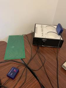
4. DMI board for digital photos

5. Harmony Evolution Chip to create more effective frequencies

6. Metapathia Hunter 4025, Biofilia, Hadoscan scanners

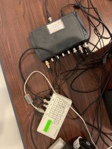
The photo above shows a DMI board properly placed on an SG1 transmitter. Our lab systems have SG8 amplifiers so that we can run up to 8 SG1s with one F165 frequency generator. Scanner earphones are placed on top of the SG1/SG2 and DMI.

The PDF in the link below shows exactly how to place a DMI on top of an SG1/SG2. Geometry is critical. Our labs use velcro tape to attach the DMI to the SG1 so that it can easily be adjusted to the optimal angle. The wrong angle or positioning will result in reduced or no effective frequency transmission!

For maximum power output the SG1/SG2 input port must be pointed towards magnetic north. The magnetic fields in your location are often distorted by buildings or machinery. Ask for a consult to get this right at [email protected] to make sure your system works properly.

The PDF also shows how to insert a Harmony Evolution Chip under the DMI for maximum response. Some trolls on the internet have complained that the Harmony Chip is useless. I make no claims for the Harmony Chip except to state that my testing shows my lab setup is about 10 times as effective as a lab without the chip.

Do your own testing!

If you have an SG8 amp, you can power up to 8 SG1s from a single frequency generator. In this case, you need only one Harmony Chip placed on the SG8 to affect up to 8 SG1 transmissions.

If you need assistance with equipment contact [email protected] and we will connect you with Longevity Research, LLC for hardware. They sell all our equipment. Frequency Research Foundation does not sell any equipment, only frequency data for use with recommended equipment. This allows us to be impartial about what equipment to use. We are only interested in what works the best given currently available hardware.

Frequency Research Foundation offers a consulting service to help you set up the equipment (highly recommended). Poor configuration can result in little or no signal output. Request a consult an [email protected].

Click here for PDF on how to setup your lab properly…

ABPA – Frequency Foundation Standard Configuration

The Frequency Foundation has spent a decade of research on fine tuning ABPA hardware for frequency transmission. We assisted in the development of special cabling and green antennae boards that are factory approved. Many different hardware addons have been tested and the Harmony Evolution chip has proven the most useful in improving effectiveness.

The configuration of the ABPA system is extremely important to get maximum benefit. A recent discovery showed that it and the green antennae add-on work best when aligned with magnetic north. Below is a photo of an ABPA connected to the green antenna and to the factory approved Blue Connector that attaches to the F165 frequency generator.

The photo on the left shows the F165 connected to an SG-8 which can power up to 8 SG1s or ABPAs. The SG8 is connected to the Blue ABPA connector in the photo on the left.

While any frequency generator such as the FSCAN can be connected to the ABPA, the F165 frequency generator has been the most useful because of its programmability along with the quality of its signal and its output of mulitple channels. This device is recommended for anyone who wants to get the most utility out of the ABPA. It is mandatory for those wanting to use Lyme frequencies as the sets are so complex it is not feasible to manually program them on another device.

It is also essential to set up the hardware exactly as indicated here. Failure to do this will seriously degrade the output of the ABPA. For those able to test the ABPA signal who find an improved configuration, the Frequency Foundation will test that configuration at no charge and confirm your findings. Otherwise use the standard configuration shown here.

In 2007, ABPA’s were upgraded with a new chip. See user manual. This means:

– More ABPA internal memory
– More comprehensive internal ABPA software

A frequency generator can be attached to an Advanced BioPhoton Analyzer (ABPA) and the device will transmit an ultralow frequency carrier wave with the generated frequencies superimposed and filtered by a target photo. The person in the photo acts as a tuner that receives the frequencies.

F165 frequency generators are used for this purpose as they put out multiple channels of high quality signals that are programmable by a scripting language. This allows you to target precisely and simultaneously all or most of the frequencies for a parasite, for example, which typically has 4-8 frequencies. This full scale assault on the life form radically shortens treatment time. Similarly for bacteria that form communities which have multiple frequencies for different stages of the community life cycle.

The recommended hardware setup has evolved over the years to make it more than 1000 times as effective when I first discovered the capability of the ABPA to transmit frequencies. It is critical that the hardware be set up exactly right to get the desired effects. Only with precisely the right hardware configuration and precisely the right frequencies can you get consistently good results.

The following switches/connectors are available on the F165 frequency generator:

1. The black knob turns up the voltage of the signal to a maximum of 16 volts for the output port directly to the right of the knob.
2. The output port to the right of the knob needs to be connected to the factory approved cable with a blue box in the center. When the other end of the cable is plugged into the ABPA, a red LED lights up on the ABPA side of the blue box. The knob is turned up so that the red LED on the F165 side of the blue box exactly matches the brightness of the LED on the ABPA side. This matches the impedance of the frequency generator signal to the ABPA and provides maximum effectiveness. The factory cable improved output by a factor of 5 over previous strategies of placing an ABPA wire connected to the F160 under the ABPA input well.
3. The second output jack to the right of the black knob is a 5 volt output suitable for driving Rife plasma devices.
4. The next jack to the right is for a USB cable to connect to a computer. A computer is used to program the F165 and can drive the device directly or download a program into the F165 so that it can run stand alone.
5. Next we have a power jack.
6. To the right of the power jack is an on/off switch.

A second factory approved option for the ABPA that has been developed by the inventor for use in frequency applications is a green antenna board (see photo above). It improves the effectiveness of ABPA frequency transmission by a factor of 10. (Call Dale Fawcett for ABPA accessories, F-Scan or Transfer Factor info at 360 598-6585). The effects of the cable and the antennae are multiplicative. You get 50 times the effectiveness of a frequency transmission compared to a system without them.

The Advanced Biophoton Analyzer (ABPA)is a device that can be used for many purposes. One of them is to broadcast frequencies on a very low frequency carrier wave that can penetrate the earth and is independent of distance. The frequency effect on a living organism at a remote location is comparable to being in the room with an EMEM plasma device or directly connected to electrodes from a contact device like an FSCAN when all recommendations on hardware setup are followed.

The recommended setup of the ABPA is show in the photo above:

1. The switches are set from left to right – off, off, off, auto, auto, on, send, auto.
2. The first jack on the front right of the ABPA is for power.
3. The second jack is a mini female phono jack for input. The recommended setup is a MONO mini male dual phono jack that connects both the antennae and the factory approved cable with the blue box to the ABPA. Do not use a stereo dual phono jack as the ABPA will receive no signal and the ABPA will not transmit frequencies.
4. A Polaroid photo of the target should be put on the antenna. For high power transmission, it is recommended that a high resolution digital photo in a DMI which is inserted into the photo well. This combination will increase the effectiveness of the transmission by another factor of 5 or more. This gives us 5x10x5 times the effectiveness of earlier implementations.
5. Finally, a Harmony Evolution Chip should be put on the antennae. This improves the output of the ABPA by another factor of 25 so we have a system that is 5x10x5x25 or thousands of times better than the first implementation of these systems.
6. There are proprietary hardware strategies that the Frequency Research Foundation uses to enhance output even further, making remote transmission as effective as local application of frequencies in most cases.

The ABPA has some advantages over direct contact with frequency devices as it is able to monitor the energy system of the target and only transmit information that will balance that energy system and bring it into a higher energy state. It is a self-correcting device that works with and enhances the effect of frequency generators attached to it. This only occurs if a Polaroid photo of the target is in the circuit. It can be in the photo well, on the antenna, or in the input or output wells. All of these are on the same circuit.

The only challenge remaining is finding the right frequencies for your purposes. As Dr. Royal Rife once said, if you have the wrong frequency or set of frequencies you will get no effect. For help in finding the right frequencies for your needs, contact the Frequency Research Foundation.